- Contact Person : Ms. Wang Sophie
- Company Name : Jinan Tianchen Testing Machine Manufacturing Co., Ltd.
- Tel : 86-531-88606113
- Fax : 86-531-88607888
- Address : Shandong,JINAN,TIANCHEN INDUSTRIAL PARK, TIANCHEN ROAD, HIGH AND NEW TECH DEVELOPMENT ZONE, JINAN
- Country/Region : China
- Zip : 250101
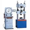
DIAL TYPE HYDRAULIC UNIVERSAL TESTING MACHINE
Detailed Product Description
1. Application and Scope
Its designed for tensile testing of safety belt, is suitable for use in science and research institutes, colleges and universities, quality inspection center, and commodity inspection, is a kind of ideal testing machine to meet requirement of
manufacture, research, and teaching etc industries. It is designed and
manufactured according to ISO 7500/1-- 1999 .
2. Technical specifications
a Max. load capacity :1000kN
b Measuring range: 0-200kN, 0-500kN, 0-1000kN c Accuracy of Indicating Value of Testing: ±1% Machine Grade : 1
c Max. distance between grips(include pistons stroke) :600m
d Max. distance between upper and lower platen: 500mm
f Size of upper and lower platen: 204 x 204mm
g Max. stroke of piston : 250mm h Clamping range of round specimen: 16-52mm
9.Clamping range of flat specimen: 16-48mm
i Max. clamping width of flat specimen: 82mm
j Adjustable rate of lower crosshead 300mm
k Overall dimension of testing machine(L x W x H) Load frame(including Max. stroke of piston) 980mmx650mmx 2220mm Dynamometer 10750 x 8170 x1730mm
3.Working Environment
The testing machine operates normally in following conditions:
a.Ambient temperature: 10-35 ;
b.Relative humidity: ≤80%;
c.Around it without vibration, corrosive medium, and interference of strong magnetic field;
4.Construction
4.1Load Frame
It consists of base, bench, upper and lower crosshead, grips, lead-screw, and columns. Bench and upper crosshead, via columns, construct a rigid frame, and Bench and principal working piston are connected through screws, which forms two working spaces, thats: tension space between upper crosshead and lower crosshead, and compression space between lower crosshead and bench. Tension space and compression space are adjusted through movement of upper and lower crosshead. Lower crosshead is moved through a system consisting of motor, deceleration device, chains transmission mechanism, and lead-screw
couples. The space between upper grip-socket and lower grip-socket is used for tension. Grip is set in socket. Different test is done through changing different grips. The working oil cylinder and the piston are the main parts of machine frame. Their contact surface are precisely machined and has certain clearance to ensure free
movement and minimum friction. When the high pressure oil is delivered to the oil cylinder, it lifts the test bench with the crosshead, and load is transferred onto the specimen gradually. Special attention, therefore, should be paid to the cleanness of oil. Impurities and chips contained in oil are not allowed to enter the cylinder through the pump, valves and pipes, for they will damage the contact surfaces of oil cylinder and piston. Furthermore, they may affect the accuracy of test.
4.2Dynamometer
The dynamometer is composed of load indicator, control valves, automatic tracer, high pressure oil pump and motor, load measuring devices, buffer valve and electric part. The structures of load indicator, control valves, and automatic tracer see figure 3.
4.2.1Load Indicator
The indicator scale of dynamometer is enclosed in a glass cover. Three different measuring scales are available on the dial. The graduation of each scale can be read clearly and accurately. Also, enough space between adjacent division is provided to facilitate estimation to one fifth of each division. Two pointers for indicating the load are provided on the dial: one is a driving pointer and the other is a driven pointer.During test, the driving pointer with the driven pointer will revolve clockwise as the test load increases. After test the load is released and the driving pointer will return to zero while the driven pointer still remains in order to provide enough time for an accurate reading of the load, the position of the driven pointer can be adjusted by operating knob fitted outside the glass cover.
4.2.2 Controls
Start-stop pushbutton of the motor for pump and the power pushbutton and pilot lamp are fixed on the control desk. Inlet valve, also known as pressure adjusting valve, is provided for both producing high pressure of oil pumped into the working cylinder and controlling the speed of increase or decrease of load. A return valve serve to release the load and return oil in the working cylinder to oil tank.
4.2.3 Automatic Tracer
An automatic tracer consisting of a recording pen, a guide bracket and a recording drum, is mounted on the upper right side of the pendulum dynamometer. A roll of recording paper(295 x 210mm) is reeled upon the recording drum where a stress-strain diagram will be drawn automatically by means of recording pen held by holder. The strain of specimen will be transmitted to the recording drum by a cord which reeled a round one of three grooves on the left of the recording drum, while a counter-weight is hung at the other end of the cord. The recording drum should revolve towards the operator while standing in front of the dynamometer during operation. The transmission cord may be reeled on the large, medium or small groove of the recording drum so that the strain curve recorded will be in the proportion of 1:1, 2:1, and 4:1 to the actual strain as required. It should be mentioned that the diagram proportion is not sufficient for precision measuring of deformation curve. Therefore, this tracer is used only for obtaining reference data and other unimportant tests.
4.2.4 High Pressure Oil Pump and Motor
The oil pump and electric motor are coupled together by a v-belt which are housed on the base of the dynamometer. An oil tank is provided inside the base and the oil level in the tank can be observed through a sight glass from outside the oil tank. The oil pump is adopted of an axial plunger pump which comprises sets of pistons. The piston and cylinder of the pump have high surface finish and fine fitting surface to ensure production of high oil pressure with minimum leakage.
4.2.5Load Measuring Device
Load-measuring cylinder has load measuring piston which travels in conjunction with worm gear through fixture. When the pump is started, the sliding movement of the piston in the cylinder is converted into dynamic friction to improve the sliding performance of the piston. The fitting surfaces of the cylinder and the piston are precisely finished and has sliding clearance between them. After the machine is properly adjusted, the proportion of the cross section of the load measuring piston to that of the working piston of load frame is constant, thus the total load applied on them is directly proportional to the areas of their cross section. When the oil pressure acts on the piston, it will move downward. And it will make the main spindle to drive the pendulum to produce an angular displacement. The pointer of the dial will be rotated by the angular displacement which is in direct proportion to the load applied on the piston, and indicates the load applied on the specimen.
4.2.6Electric Part :Electric circuit diagram sees Figure 6. Electric connection Diagram sees figure 7. When repair or trouble shooting is done, must cut off power outside machine. Nonprofessionals dont check electric part.
4.3 Hydraulic: System Oil is sucked into the oil pump via filter and is delivered to the inlet valve through pump outlet pipe of the pump. With the inlet hand-wheel closed and the piston pushed open oil flows to oil tank through the inlet pipe. When the inlet hand-wheel is opened, oil goes to the working oil cylinder through inlet pipe and further to the load measuring oil cylinder through pressure pipe and return valve body.


